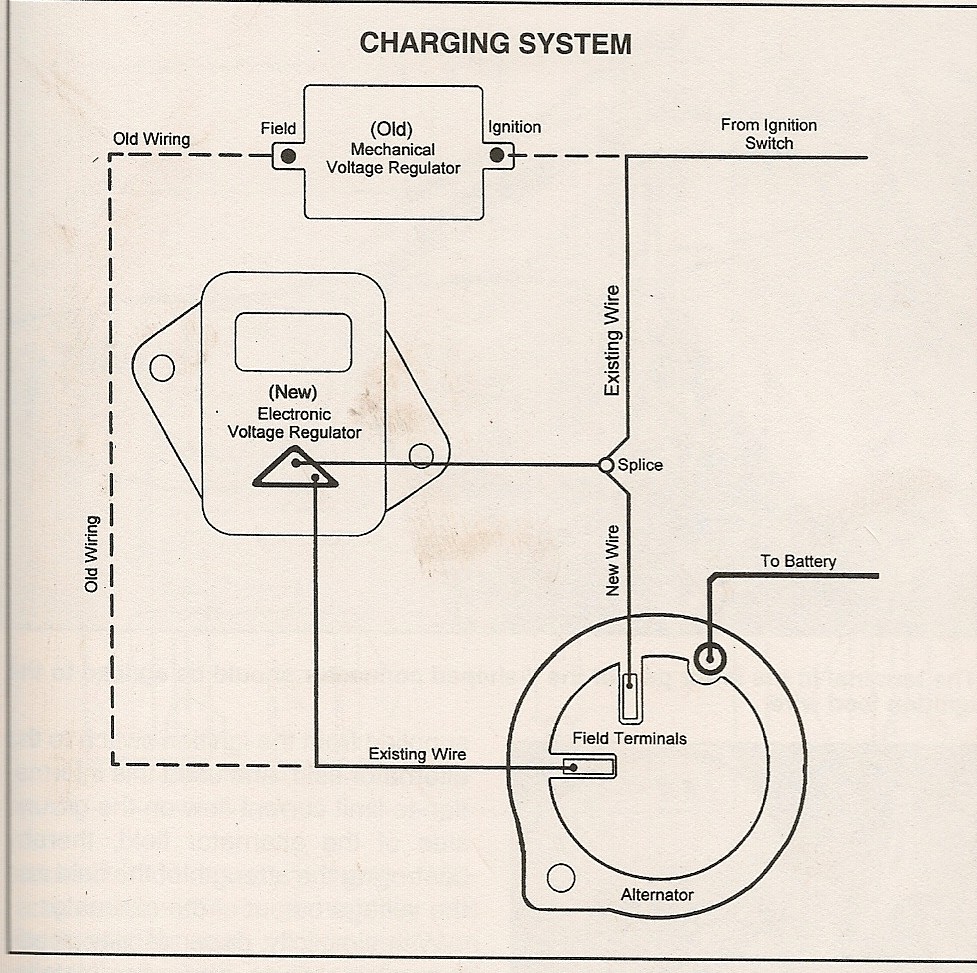
Ford External Regulator Wiring Diagram is a crucial tool for understanding the electrical system in Ford vehicles. It provides a visual representation of the wiring layout, connections, and components involved in regulating the voltage output of the alternator. By following the diagram, mechanics can easily identify and troubleshoot any issues related to the external regulator.
Importance of Ford External Regulator Wiring Diagram
- Helps in understanding the electrical system of Ford vehicles
- Aids in diagnosing and fixing voltage regulation problems
- Ensures proper connection of wires and components
- Saves time and effort in troubleshooting electrical issues
Reading and Interpreting Ford External Regulator Wiring Diagram
When looking at a Ford External Regulator Wiring Diagram, it is essential to understand the symbols and colors used to represent different components and connections. The key to effectively interpreting the diagram is to follow the wiring paths and identify the functions of each wire and terminal. By familiarizing yourself with the diagram key, you can easily trace the voltage flow and pinpoint any potential issues.
Using Ford External Regulator Wiring Diagram for Troubleshooting
- Identify the external regulator, alternator, and battery connections on the diagram
- Check for continuity and voltage readings at various points to diagnose problems
- Refer to the wiring diagram to ensure proper wiring and connection of components
- Use the diagram to trace the voltage path and identify any open circuits or shorts
Safety Tips for Working with Ford External Regulator Wiring Diagram
Working with electrical systems can be hazardous, so it is crucial to follow safety precautions when using wiring diagrams:
- Always disconnect the battery before working on the electrical system
- Avoid working on live circuits to prevent electric shock
- Use insulated tools to prevent short circuits and damage to components
- Refer to the vehicle’s service manual for specific safety guidelines and precautions
Ford External Regulator Wiring Diagram
Ford External Regulator Wiring Diagram

Ford Voltage Regulator Wiring Diagram

Ford External Voltage Regulator Wiring Diagram

1979 Ford Voltage Regulator Wiring

Voltage Regulator Wiring Diagram Ford – Wiring Diagram Schematic

Wiring Diagram For Ford External Voltage Regulator – Wiring Diagram
