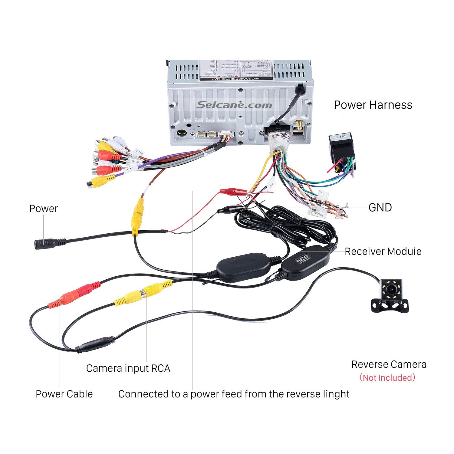
Ford Backup Camera Wiring Diagrams are crucial tools for understanding the electrical connections and components within a vehicle’s backup camera system. By following these diagrams, mechanics and DIY enthusiasts can effectively troubleshoot, install, or repair backup cameras in Ford vehicles.
Why Ford Backup Camera Wiring Diagrams are Essential
- Helps understand the wiring connections of the backup camera system
- Aids in troubleshooting electrical issues
- Assists in proper installation and repair of the backup camera
How to Read and Interpret Ford Backup Camera Wiring Diagrams
When looking at a Ford Backup Camera Wiring Diagram, it’s important to pay attention to the symbols, colors, and lines used to represent different components and connections. Here are some tips for effective interpretation:
- Identify the power source and ground connections
- Follow the wiring paths to understand the flow of electricity
- Refer to the legend or key for any unfamiliar symbols
Using Ford Backup Camera Wiring Diagrams for Troubleshooting
When facing electrical problems with a Ford backup camera system, the wiring diagram can be a valuable resource. Here’s how you can use it for troubleshooting:
- Check for continuity and proper voltage at different points in the wiring
- Compare the actual wiring with the diagram to identify any discrepancies
- Isolate the problematic component or connection based on the diagram
Working with electrical systems can be dangerous if not done properly. It’s important to prioritize safety when using Ford Backup Camera Wiring Diagrams. Here are some safety tips to keep in mind:
- Always disconnect the vehicle’s battery before working on the electrical system
- Avoid working on wiring when the vehicle is running or the key is in the ignition
- Use insulated tools to prevent electrical shocks
- Double-check your work before reassembling components to avoid short circuits
Ford Backup Camera Wiring Diagram
2011 Ford F150 Backup Camera Wiring Diagram

Wiring A Backup Camera

Ford F-150 Backup Camera Installation + Kit 2015 – 2019 | Complete

Ford F250 Backup Camera Wiring Diagram

2016 Ford F250 Backup Camera Wiring Diagram For Your Needs
Ford F350 Backup Camera Wiring Diagram – Wiring Site Resource
