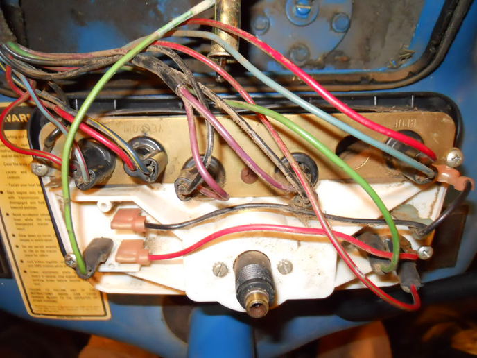
When it comes to troubleshooting electrical problems in a Ford 5000, having access to the instrument cluster wiring diagram is essential. This diagram provides a visual representation of the electrical connections within the instrument cluster, helping mechanics and DIY enthusiasts pinpoint issues and effectively make repairs.
Why are Ford 5000 Instrument Cluster Wiring Diagrams Essential?
Instrument cluster wiring diagrams are essential for several reasons:
- Help identify the various components within the instrument cluster
- Show the connections between these components
- Aid in diagnosing electrical issues such as faulty connections, blown fuses, or short circuits
How to Read and Interpret Ford 5000 Instrument Cluster Wiring Diagrams
Reading and interpreting instrument cluster wiring diagrams can be daunting for beginners, but with practice and a basic understanding of electrical systems, it becomes easier. Here are some tips:
- Start by familiarizing yourself with the symbols and colors used in the diagram
- Trace the circuits from the power source to the components to understand the flow of electricity
- Note the connections and potential points of failure
Using Ford 5000 Instrument Cluster Wiring Diagrams for Troubleshooting
Instrument cluster wiring diagrams are valuable tools for troubleshooting electrical problems. Here’s how you can use them effectively:
- Identify the specific issue you are facing, such as a malfunctioning gauge or warning light
- Refer to the wiring diagram to locate the relevant components and connections
- Use a multimeter to test for continuity, voltage, and resistance at key points in the circuit
Importance of Safety
Working with electrical systems can be hazardous, so it’s crucial to prioritize safety. Here are some safety tips and best practices:
- Always disconnect the battery before working on the electrical system
- Use insulated tools to prevent electrical shocks
- Avoid working on wet surfaces or in damp conditions
- If you’re unsure about a particular step, seek help from a professional mechanic
Ford 5000 Instrument Cluster Wiring Diagram
Ford 5000 Instrument Cluster Wiring Diagram

[21+] Ford 5000 Instrument Cluster Wiring Diagram, Instrument Cluster
![Ford 5000 Instrument Cluster Wiring Diagram [21+] Ford 5000 Instrument Cluster Wiring Diagram, Instrument Cluster](https://i1.wp.com/i.imgur.com/0evd61U.jpg)
[21+] Ford 5000 Instrument Cluster Wiring Diagram, Instrument Cluster
![Ford 5000 Instrument Cluster Wiring Diagram [21+] Ford 5000 Instrument Cluster Wiring Diagram, Instrument Cluster](https://i1.wp.com/ww2.justanswer.com/uploads/djenn434/2009-11-25_210934_radio_0000.jpg)
Ford 3000 Instrument Panel Wiring – Yesterday's Tractors

[21+] Ford 5000 Instrument Cluster Wiring Diagram, Instrument Cluster
![Ford 5000 Instrument Cluster Wiring Diagram [21+] Ford 5000 Instrument Cluster Wiring Diagram, Instrument Cluster](http://i293.photobucket.com/albums/mm45/6054Ken_C/97 F250 HD 73 powerstroke 4x4 cc sb e4od auto/InstrumentClusterIllumination.jpg)
[21+] Ford 5000 Instrument Cluster Wiring Diagram, Instrument Cluster
![Ford 5000 Instrument Cluster Wiring Diagram [21+] Ford 5000 Instrument Cluster Wiring Diagram, Instrument Cluster](http://ww2.justanswer.com/uploads/MO/molurch/2013-08-01_132552_ip.png)