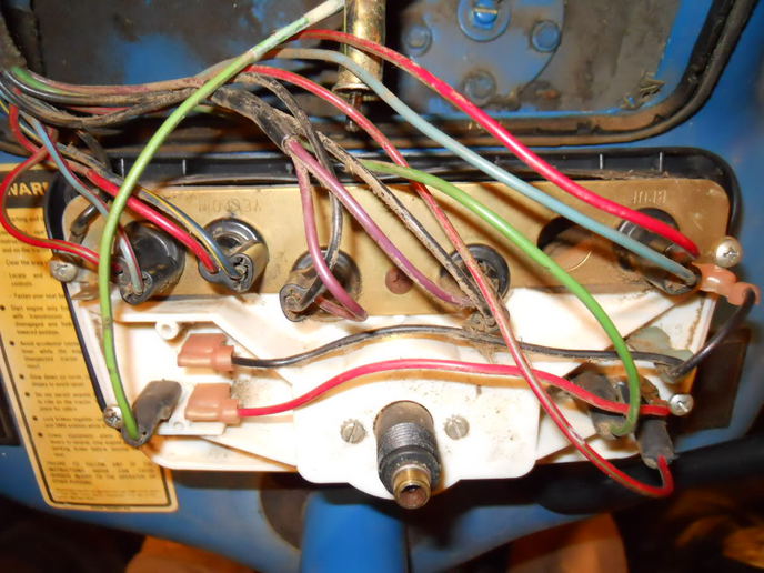
When it comes to understanding the electrical system of a Ford 4000 tractor, the Instrument Cluster Wiring Diagram is a crucial tool. This diagram provides a detailed layout of the wiring connections within the instrument cluster, allowing mechanics to troubleshoot and repair electrical issues effectively.
Why are Ford 4000 Instrument Cluster Wiring Diagrams essential?
- Help identify the various electrical components within the instrument cluster
- Show the specific wiring connections and paths
- Aid in diagnosing electrical problems quickly and accurately
- Ensure proper installation of new components
How to read and interpret Ford 4000 Instrument Cluster Wiring Diagrams effectively
Reading and interpreting wiring diagrams can be daunting for some, but with a little guidance, it becomes much easier. Here are some tips to help you navigate through the diagram:
- Understand the symbols and abbreviations used in the diagram
- Follow the wiring paths from one component to another
- Pay attention to color codes for wires
- Refer to the legend for any additional information
Using Ford 4000 Instrument Cluster Wiring Diagrams for troubleshooting electrical problems
When faced with electrical issues in your Ford 4000 tractor, the Instrument Cluster Wiring Diagram can be your best friend. Here’s how you can use it to troubleshoot problems effectively:
- Identify the specific component or circuit that is malfunctioning
- Follow the wiring diagram to trace the problem back to its source
- Check for loose connections, damaged wires, or faulty components
- Refer to the diagram for proper testing procedures
It’s important to note that working with electrical systems can be dangerous if proper precautions are not taken. Here are some safety tips to keep in mind when using wiring diagrams:
- Always disconnect the battery before working on the electrical system
- Use insulated tools to prevent electric shocks
- Avoid working on the wiring when the tractor is running
- Double-check all connections before reassembling components
Ford 4000 Instrument Cluster Wiring Diagram
Ford 4000 Instrument Cluster Wiring Diagram

Ford 4000 Instrument Cluster Wiring Diagram

4600 instrument cluster wiring – Ford Forum – Yesterday's Tractors

Ford Instrument Cluster Wiring Color

Ford 3000 Instrument Panel Wiring – Yesterday's Tractors

Ford Tractor Electrical Wiring Diagram
